
Interface and Software
Interface and Control Module
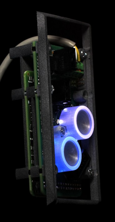
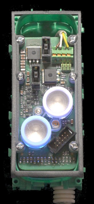
Until the final IC is available, Innovatic can offer an interface and control module - Max-i IF2, which comply with specifications 13 - 16 and also includes a power supply, which may be used to supply external circuitry. The module simulates a Max-i IC by means of an FPGA, a serial EEPROM for parameter storage and discrete components for the line interface. This solution may be very interesting for vendors and makers, who want to take the step into the future and even have a possibility to influence the standard before the IC is made. It may also be interesting for semiconductor companies, who may be looking for a new product family and/or can see the enormous potential in one fieldbus for virtually all low to medium speed applications from the most price sensitive ones to the most demanding. Max-i is for example the ideal replacement for 4-20 mA and HART communication. It has the potential to be cheaper, it is much faster, it does not sacrifice the accuracy, it can save a lot of cabling, and it does not give wrong readings if moisture penetrates the cabling or junction boxes.

Module specification:
- Dimensions: 80 mm x 41.4 mm.
- Temperature range: -40°C - 85°C (-40°F - 185°F).
- Recommended operating voltage range according to specification 13 and 14: 15.4 V - 24.6 V.
- Absolute maximum voltage range: -30 V (reverse polarity protected) - 40 V (transient conditions).
- Inputs: 8, 5-V-tolerant schmitt-trigger inputs with 10 kΩ pull-down resistors.
- Outputs: 8 + 1, 3.2 V (at 25°C, 77°F) outputs with 10 mA drive capability, which intentionally have a negative temperature coefficient of approximately -1.8 mV/°C (-1 mV/°F). This makes it very easy to make temperature compensated current generators, drivers and wire-OR gates by means of a single NPN-transistor and a resistor per channel - plus a PNP booster in case of current levels above approximately 350 mA.
- Power supply: Switch capacitor with a 5 V output and a 5-V-OK status signal, a 3.2 V output with the same negative temperature coefficient as the 8 outputs and a 6-Vpp 280 kHz square wave, which can be used to generate positive and negative voltage levels for example for RS-232 and to drive a transformer if a galvanic separation is needed. The maximum current of all outputs together including basis currents to external output transistors is 100 mA, but due to thermal limitations, it must be derated with 10 mA/V above 20 V and 1 mA/°C, 0,56 mA/°F above 25°C, 77°F. Therefore, it is not useable if the full recommended operating range is needed (24.6 V and 85°C, 185°F).
- I/O connection: 32-pole dual-entry socket (female) connector, which is also used for firmware programming and updates.
Lamp Control Module
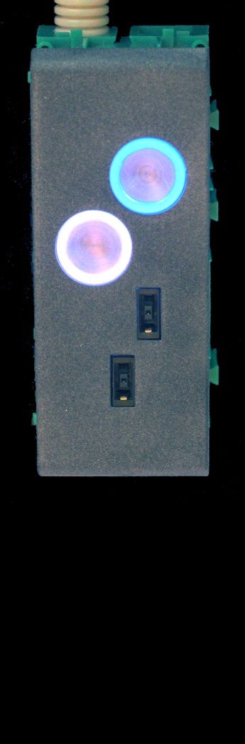
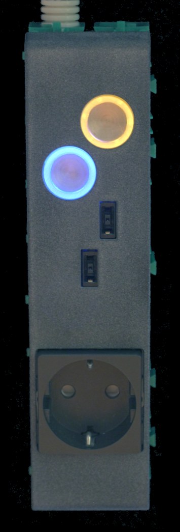
An overlay board LS1 is also available, which makes it possible to control two lamps or group of lamps by means of touch control with light indication as shown below:
Module specification:
- Dimensions: 97 mm x 41.4 mm.
- Temperature range: -40°C - 40°C (-40°F - 104°F).
- Absolute maximum voltage range: -30 V (reverse polarity protected) - 40 V (transient conditions).
- Outputs: Two 20-V, Slim-tip outlets, which are both power and current limited to maximum 100 W and 8 A according to the IEC 60950-1 safety standard and inrush current limited to maksimum 5 A/ms even in case of a short circuit. By means of jumpers, the center pin in each outlet can be selected to either a COM conductor for communication or a 560 Ω resistor to ground, which tells a Lenovo computer (uses also Slim-tip) that the maximum charging power is 90 W, which fits perfect with the power limitation with the necessary tolerances.
- Operation: Toggle touch control. Maximum 10 kV ESD voltage.
- Light indication: Blue = off (<6 mW power consumption), Amber = Lamp-on (<20 mW), White = Group-on (<26 mW). In the event of a short circuit on any of the two 20-V outlets, the corresponding light indication - upper for upper outlet and lower for lower outlet - is switched off and it is then necessary to remove the plug to reset the electronic fuse.
The module may be mounted in an LK FUGA 50 mm IP20 wall box and may be combined with a mains voltage outlet like Schuko as shown below:
Modem Module
This module makes it possible to control Max-i by means of a galvanically separated RS-232 port and/or a galvanically separated USB-B port (one port at a time) by means of a MaxLinear XR21B1411 UART. The module includes status LED's for 20 V and internal 5 V, two LED's to indicate transmission and collision and a 20 position LED bar graph as a speedometer, which shows the relative bus load on the line (50 % on the picture below).

Communication to Computers
Like for example DMX512 and LIN, Max-i uses asynchronous UART communication with "Break" to separate telegrams. This is the most efficient way for Max-i, which uses synchronous binary communication on the bus where all byte values from 0 to 255 are possible (no code left for separation). To be able to hold back the communication when the bus is busy and/or there are many 1-bits to transfer (1-bits are up to 3 times longer than 0-bits), Max-i uses automatic flow control based on CTS.
Although asynchronous UART communication is an over 40 years old de-facto standard, it is unfortunately still not supported very well in the PC-world.
First of all, the transmitter FIFO in the standard UART 16550 of the PC world has always been full of errors and flaws. In the first version, the transmitter FIFO didn't work at all although the circuit was marketed! In the next version (16550AFN), the FIFO almost worked, but a byte written while the last byte was transmitted, was not always recognized so that you could lose bytes. In the following versions, this bug was fixed, but except for Texas Instruments, the designers still did not realize that a transmitter FIFO without automatic flow control is useless in practice, and although there are plenty of newer and much better designs like 16C650, 16C750, 16C850 and 16C950, most chip sets in the PC-world "of course" still use the buggy one after 40 years.
The receiver FIFO in 16550 is cleverer as it is 11 bit wide to enable 100 % synchronization between the received bytes and the three error and status flags - Break, Framing Error and Parity error, but with a little "help" from Microsoft that feature is efficiently destroyed! SerialPort in Microsoft .Net takes 11 bits from the FIFO, use the three status bits to fire some events, which may be executed much later, and then throws them away, before the result is stored in a 16-bit stream, which could easily have contained all 11 bits. This makes it impossible to use any of the modern communication methods like 9th bit communication and telegram separation by means of Break because the vital synchronization between bytes and flags are lost and cannot be regained. This also means that in case of an error, all received bytes in the receiver FIFO and any following buffers must be discarded because it is impossible to tell to which telegram an error belongs!
To make it complete, .Net only has two flow control options - None and CTS, but it is not possible to specify whether CTS shall be handled in hardware or in software, which may be too slow. This is a very big problem on some computers. Besides, there is no event when the transmitter serial register becomes empty (if this is possible) so it may be necessary to listen to one's own communication to control the modem signals in a reliable manner. .Net also pass all signals through at least one level of task switching so that it for example is impossible to generate Break conditions shorter than 11-16 mS unless it can be done in hardware. At a speed of just 9.6 kbps this is as much as an entire 5-byte message and at for example 125 kbps it corresponds to over 4, 9-byte messages so it is a very big loss of transmitter efficiency.
The UART in many microprocessors are not much better. For example, the Renesas RA4M1 processor in the new Arduino UNO R4 WiFi has a receiver FIFO that at first appears to be 16 bit wide and therefore fine; but it is actually only 9 bit wide and the upper 6 status bits are just a copy of the status register where each error bit needs to be reset manually once it is set. This of course saves some gates, but it makes it impossible to use Break to separate telegrams as every byte in the FIFO will be marked as having a framing error once the Break-byte has been received, and in case of an error on a byte, the content of the entire FIFO must be discarded like in Microsoft .Net because it is impossible to tell to which telegram the error belongs. If the designer of the UART had just made a possibility to replace the 9th bit of 9-bit frames with the framing error bit for the present byte, a 9-bit wide FIFO would still have been enough for the majority of applications, which use 8-bit data, and the UART would have been usable for Max-i, LIN, DMX512 and other bus systems, which use Break. Very often you also see 8-bit UART's on 32-bit processors where you have to read the status and data separately, insertion of a Break is usually not delayed until the transmitter FIFO is empty and most DMA transfers require that the data length is known in advance although this is impossible on the receiver side.
9-bit communication has been considered, but rejected due to many problems:
- It is not supported by SerialPort of Microsoft .Net and the 16C550 - 16C750 series of UART's. This makes it useless in the PC-world and this alone makes it out of the question.
- It is not supported by DMX512 lighting controllers. Such controllers can drive Max-i directly at 250 kbps if automatic flow control is added, which may be very simple to do in hardware.
- Most other communication systems such as Ethernet use a stream of 8-bit data, which is then divided into frames. Such a stream can easily be transferred to Max-i by means of an 8-bit wide FIFO (or DMA), and the framing can then be replaced with an added Break when the FIFO is empty and there are no more data to load. With 9-bit communication, a 16 bit FIFO is needed and every byte has to be expanded and the last one marked as a frame delimited. This makes it impossible to use the content of a FIFO before the entire message has been received and the last byte marked, which completely destroys the purpose of a FIFO.
USB-Serial Converters
Today, most PC's do not have an RS-232 or RS-485 port and may not even have space for an extension board, so it is very common to use USB-serial converters, but some precautions are necessary depending on the manufacturer:
Devices from Future Technology Devices International Ltd. (FTDI) like the FT232(x) series:
These devices are not recommended.
- Although the data sheet claims that the devices support Break detection, this support is so limited that it is useless in practice. The receiver FIFO is only 8 bit wide and every time a special event occurs, this is reported in the first byte of a USB transfer. Unfortunately, "Break" is not an "event character" so in case of more telegrams immediately after each other, it is impossible to separate the various telegrams and even if it were, the very short telegrams of Max-i would course so many USB transfers that the maximum speed would be rather limited.
- When used together with SerialPort of Microsoft .Net, more break events are sometimes reported than actually transmitted, and the state of CTS is not reported correct except just after initialization of the driver.
- Although the data sheet claims that there is automatic flow control, this is only partly true. When CTS goes low, the devices may continue to transmit up to 3 bytes more, which is too much for the Max-i controller, which only has a 3-byte FIFO where one byte is the UART shift register. In practice, all telegrams course overflow except for a poll of a value with a short identifier! Note that most microprocessors with build-in UART have an even shorter FIFO than Max-i - usually only a single register, so the FTDI devices are as useless for communication with these kind of devices as they are for communication with Max-i.
Devices from MaxLinear (previous EXAR) like the XR21V141x, XR21B1411 USB-UART family:
The MaxLinear family has a 384 x 11-bit receiver FIFO and a 128 x 9-bit transmitter FIFO. They also have a Wide-mode i hardware where the devices transfer two bytes for every byte received - one with data and one with status. In this way, it is possible to work around the Microsoft limitation and use advanced communication methods, but unfortunately the two bytes are not marked as status and data so it is possible for the communication to get out of synchronization. The devices are also able to force a USB transfer if a period corresponding to 3 bytes has elapsed without any reception and it can generate a timed Break, which, after all, is better than a software controlled Break, but there are still some problems:
- If a timer value is written to the TX_BREAK register, a Break with the specified time is generated as soon as the serial register (TSR) gets empty and no matter the state of CTS! This means that if there are any data in the FIFO, the Break will be generated before the last byte has been transmitted, which will destroy the message, and since Break does not take CTS into account, it may even cause an overflow in the Max-i controller! This is certainly not very clever. For devices like debuggers and controllers for traffic lights, which do not need to communicate continuously, it is however possible to work around this problem by sending Break before the message and not after. The controller just needs it to separate the various messages and don't care.
- Break is not specified as a number of subsequently 0-bits, which would be the ony appropriate thing to do, but in milliseconds (ms). Since the minimum value is 1 ms, which will cause the time to be between 1 and 2 ms, a Break will usually take longer time than the message itself at all speeds above 76.8 kbit/s. This limits the maximum number of telegrams a factor 30 - 60 at the highest UART speed (4 Mbit/s) where a 5-byte message itself only takes approximately 32 µS!
- There is no way to tell when the serial register (TSR) is empty. It is only possible to tell when the FIFO is empty, but this does not guarantee that it is safe to send a Break when CTS is asserted because more data could be loaded in the FIFO in the meantime. If the test for FIFO empty and CTS is only done once, it fairly frequent happens that Break is activated while CTS is de-asserted, which causes an overflow in the Max-i controller. In practice, it is necessary to do the tests 3 times after each other before Break is activated to get a sufficient reliable communication for uncritical applications.
- It is not possible to use an external (x4, x8 or x16) clock for the UART so the Max-i controller needs to have a very accurate (external) clock and every time a speed is changed, it is not enough just to set it in the Max-i controllers, which is easily done by means of two common network telegrams - one to set the new speed and one to confirm it and store it permanently.
- The driver seems to be a standard Microsoft driver, which does not support any of the advanced settings in the circuits. For example, it is only possible to set the FIFO sizes up to 16 bytes corresponding to a standard 16C550 UART and it is not possible to select the wide mode.
- The driver does not fire the .Net SerialPort PinChanged event for Break characters, which makes it useless for Max-i unless the circuit is put into Wide mode. The PinChanged event works all right for DSR and CTS.
- The driver or the circuit generates numerous Break's (00 bytes) when the driver settings are changed such as port name (COMx) or flow control.
- There is no way to set the properties of the USB part like the number of 64-byte blocks for each transfer (for Max-i, this number should be 1). You can only hope that the default settings are what you want.
It is easy to utilize the wide mode by means of for example native C or C++ programming, but nowadays most Windows programmers use .Net and managed code and "of course" there is no direct way to communicate with the driver that way. SerialPort of .Net has no method to return the handle of an opened port and many types are private. The only way to get the handle is by means of a reflection hack, which gets it from the generated code. By means of this handle and a little unmanaged code it is then possible to put the MaxLinear circuits in wide mode and utilize the Break generation. It is not very pretty, but it works - at least for uncritical purposes. The combination of the block oriented USB, which does not fit very well with short messages, and the horrible Microsoft implementation of Serial Port is a very bad combination, which is not recommended for any critical purpose.
In practice, there are at least three solutions to the communication problem:
- Use a microprocessor with a good UART and an Ethernet port to interface the Max-i controller to a LAN port by means of UDP/IP. This is properly the best solution and it has the advantage that it is inherent galvanic separated by the magnetics. Besides, it enables WiFi communication to mobile devices if rare errors due to reduced speed and/or interference can be accepted. Since Max-i and other fieldbus systems cannot guarantee that all data always come through and all commands are always executed - the necessary power or pressure may for example be missing, there is no reason to use TCP and 10 Mbit/s may therefore be enough. A fieldbus system should instead check the status of the process regulary and after each command.
- Use for example a 16C950 UART from PLX Technology (previous Oxford Semiconductor) and write a driver that uses 16-bit buffers and preserves the synchronization between bytes and flags. This is also a good solution, but it will usually require an extension board, which may not be available or possible to mount.
- Use the MaxLinear XR21V141x, XR21B1411 or any newer family of USB-serial converters in Wide mode as shown in the test program and consider to send Break before the message and not after. This is good enough for debugging and user interface, but may not be good enough for example for industrial automation.
Test program
We have a small test program written in Microsoft VB.NET for framework 2.0, which is the only tested .Net version, where you can live with the bugs. It throws an unhanded exception if you remove the USB plug, but otherwise it works if the CTS flow control is fast enough, which may be a very big problem on laptop computers where this is often handled in software! If you receive "Serial-in overrun errors" (00 00 00 10 0) and see a lot of unfinished or "half" commands, you need a faster computer or one, which can handle the flow control in hardware. All newer versions of .Net up to at least 3.5 SP1 are completely useless. Microsoft tried to dig down in the "hornet's nest" to fix the bug, but didn't succeed and instead destroyed everything! You can download the entire source code as zip file here: www.max-i.org/MaxiTesterExar.zip or just the executable: www.max-i.org/MaxiTesterExar.exe . When the zip-archive is unzipped, open the folder MaxiTesterExar. You can then choose to open the VB program by clicking on MaxiTesterExar.sln or you can navigate to the exe file in MaxiTesterExar/bin/Release/MaxiTesterExar.exe. The test program will be updated from time to time as new features are added, but the version should be at least V13 to be usable with specification 13.x and 14.x (check the name in the upper left corner of the form).
The test program is default in MaxLinear/EXAR XR21B1411 USB-serial converter wide mode. In this mode, all telegrams are separated correct except for a very slight probability of misplaced Breaks, which destroys the messages as described above. Note that for the moment, the program is only tested with XR21B1411. It may therefore not work for newer types or with XR21V141x, which uses different register addresses.
If the UART mode is used instead, there may be problems with Break. A transfer is triggered when the Break event fires, but because Microsoft doesn't preserve the synchronization between data and flags, our test program cannot always recognize telegram boundaries in this mode. At low telegram rates it works quite well, but at higher rates, it is not able to separate the various telegrams. Note that if you try to use the program in this mode together with a MaxLinear USB-serial converter, you will not receive anything as these circuits do not fire the PinChanged event when a Break occurs.
When you start the test program, you must first select the UART type (may be set already), then select the COM port in the ComboBox and then usually "CTS handshake" except for a few 16C950 UART drivers, where the handshake must be set to None in the program and to CTS handshake in the driver by means of Windows device manager (program setting not transferred to driver). At any time it is possible to change the COM port selection and the Baud rate.
The Transmitter TextBox accept any mix of ASCII characters embedded in quotation marks and hexadecimal numbers with an even number of digits like for example """Test""" 78 90 "UU" FF76. A Carriage Return (CR or Enter) is specified as its hexadecimal value 0D and a Line Feed (LF) as 0A. Note that to transmit " in an ASCII string, it is necessary to write "" - exactly as in Visual Basic. In hexadecimal mode, all spaces, CR's and LF's are ignored. In case of hexadecimal numbers with four or more digits, the numbers are transmitted with the big-endian model, that is, with the most significant part first. The Send button transmits the content of the Transmitter TextBox and the Break button generates a Break condition. The receiver TextBox always writes hexadecimal characters. Note that because both the transmitter and the receiver regard all numbers as hexadecimal, no hex specifier is used! 63 means 63 hex (99 decimal) - not 63 decimal! There is no decimal to hex conversion in the program.
The maximum telegram length is limited to 2048 bytes, but it is very easy to change if longer telegrams are needed.
This page is created with WebSite X5 and updated February 6th 2026